A half adder is a fundamental building block in digital logic circuits that performs a basic arithmetic operation on two binary inputs. It produces a sum and a carry as outputs, which are essential components in the binary addition process. Understanding the truth table of a half adder is crucial for grasping the logic behind its operation.
The half adder takes two inputs, typically labeled A and B, and produces two outputs: the sum, represented as S, and the carry, denoted as C. These outputs determine the binary result of the addition. The half adder uses logical gates, such as AND and XOR gates, to perform the combinational logic necessary for its operation.
The truth table of a half adder outlines all possible combinations of inputs and their corresponding outputs. The inputs A and B can each have two possible values – 0 or 1 – while the outputs S and C can also take on these values as well. By examining the truth table, one can identify the patterns and rules that govern the half adder’s functionality.
The truth table for a half adder contains four rows, with each row corresponding to a unique combination of inputs. The first two columns represent the input values of A and B, while the last two columns represent the corresponding output values of S and C. By analyzing the output values, one can understand how the half adder performs the addition operation and determines the binary sum and carry.
Contents
- 1 The Basics of Half Adders
- 2 Understanding the Half Adder Truth Table
- 3 Applications and Limitations of Half Adders
- 4 FAQ about topic “Exploring the Half Adder Truth Table: Unraveling the Logic of Half Adders”
- 5 What is a half adder?
- 6 How does a half adder work?
- 7
- 8 Can a half adder handle carry-over from previous additions?
- 9 What are the applications of half adders?
The Basics of Half Adders
A half adder is a digital circuit that performs the basic addition function on two inputs. It takes in two bits, called inputs, and produces two outputs: a sum bit and a carry bit.
In binary arithmetic, a bit can be either a 0 or a 1. The sum bit represents the result of adding the two input bits together, while the carry bit indicates if there was a carry generated during the addition operation.
Half adders are built using logic gates, which are electronic components that perform boolean operations. The basic logic gates used in a half adder are the AND gate and the XOR gate.
The truth table for a half adder shows all possible combinations of inputs and their corresponding outputs. The inputs are usually labeled as A and B, while the outputs are labeled as SUM and CARRY. The truth table lists the inputs in binary and the outputs as either 0 or 1.
The operation of a half adder is combinational, meaning that the outputs only depend on the current inputs and not on any previous inputs. This makes half adders useful in many digital circuits that perform calculations or manipulations on binary data.
Overall, the half adder is a fundamental building block in digital electronics, providing the basic functionality for adding two binary numbers. Its simplicity and efficiency make it an essential component in more complex circuits.
Binary Addition and Half Adders
A binary adder is a digital circuit that performs the addition operation between two binary numbers. It is an essential component in digital systems, as binary addition is a fundamental operation in computer arithmetic.
When adding two binary numbers, each bit from the two inputs is added together, along with the carry bit from the previous addition. The result is a sum bit and a carry bit as output. This addition process can be achieved using half adders.
A half adder is a combinational logic circuit that takes two binary inputs (A and B) and produces two outputs: the sum (S) and the carry (C). The truth table for a half adder has four possible input combinations, and it outputs the corresponding values for the sum and carry bits.
| A | B | S | C |
|---|---|---|---|
| 0 | 0 | 0 | 0 |
| 0 | 1 | 1 | 0 |
| 1 | 0 | 1 | 0 |
| 1 | 1 | 0 | 1 |
The half adder functions using Boolean logic gates such as AND, XOR, and OR gates. The sum output (S) is obtained from the XOR gate, while the carry output (C) is obtained from the AND gate. These logic gates perform the necessary operations to calculate the sum and carry bits based on the input bits.
By using multiple half adders and cascading them together, it is possible to perform binary addition of larger numbers. Each subsequent half adder takes into account the carry bit from the previous addition, allowing for the addition of multiple bits in a binary number.
In conclusion, half adders play a crucial role in binary addition. They facilitate the addition of single bits by producing the sum and carry outputs based on the input bits. By using a combination of logic gates, half adders allow for the construction of larger adders to perform binary addition of multi-bit numbers.
Components of a Half Adder
A half adder is a combinational digital circuit that adds two binary inputs and produces two binary outputs – sum and carry. It uses boolean logic gates to perform the addition operation.
The inputs to a half adder are two bits – A and B, representing the binary digits to be added. The output includes two bits – Sum and Carry. The Sum bit represents the result of adding the two input bits, while the Carry bit indicates if there is any carry generated during the addition operation.
A half adder consists of two main components – an XOR gate and an AND gate. The XOR gate takes the two input bits (A and B) and produces the Sum output. It performs an exclusive OR function, which means it outputs a high (1) when the inputs are different, and a low (0) when they are the same.
The AND gate takes the two input bits and produces the Carry output. It performs a logical AND operation, meaning it outputs a high (1) only when both input bits are high (1), and a low (0) in all other cases.
The half adder circuit also has two additional outputs – Zero Carry and Overflow flags. The Zero Carry flag is set to high (1) when there is no carry generated during the addition operation, otherwise, it is set to low (0). The Overflow flag is set to high (1) when the sum of the two input bits exceeds the capacity of a single bit, and it is set to low (0) otherwise.
Overall, the half adder is a fundamental building block in digital circuits, used to perform simple addition operations. It showcases the basic principles of boolean logic and demonstrates how binary inputs and outputs can be processed using logic gates.
Understanding the Half Adder Truth Table
A half adder is a fundamental building block in binary arithmetic and digital logic circuits. It is a combinational logic circuit that takes two binary inputs, adds them together, and generates two outputs: the sum and the carry.
The half adder truth table shows all the possible combinations of inputs and their corresponding outputs. In a half adder, there are two binary inputs, typically labeled as A and B, and two outputs – the sum (S) and the carry (C).
The truth table for a half adder has four rows, representing all possible combinations of binary inputs:
| A | B | S | C |
|---|---|---|---|
| 0 | 0 | 0 | 0 |
| 0 | 1 | 1 | 0 |
| 1 | 0 | 1 | 0 |
| 1 | 1 | 0 | 1 |
The binary inputs A and B represent the two bits to be added, while the outputs S and C represent the sum and the carry, respectively.
From the truth table, we can observe that the sum (S) is obtained by performing the boolean XOR operation on the inputs A and B. The carry (C) is obtained by performing the boolean AND operation on the inputs A and B.
The half adder circuit consists of two logic gates: an XOR gate for calculating the sum and an AND gate for calculating the carry. The XOR gate outputs the sum bit, while the AND gate outputs the carry bit.
Understanding the half adder truth table is essential for designing more complex arithmetic circuits, such as full adders, which can add multiple bits together. It serves as the foundation for understanding binary addition and the principles of digital logic.
Explaining the Inputs and Outputs
When it comes to understanding the logic behind a half adder, it is important to grasp the concept of inputs and outputs. In the context of digital circuits, inputs are boolean variables that represent binary digits, also known as bits. In the case of a half adder, the two inputs are typically labeled as A and B, representing the two bits to be added together. These inputs can take values of either 0 or 1, which are the two possible binary digits.
The half adder has two outputs: the sum and the carry. The sum output represents the result of the addition operation, while the carry output indicates whether there is a carry that needs to be propagated to the next stage of the calculation. Both the sum and carry outputs are boolean values, either 0 or 1, and are typically labeled as S and C, respectively.
The combinational logic function of a half adder can be represented by a truth table, which outlines all possible input combinations and their corresponding outputs. The truth table for a half adder has four rows, each representing a different input combination. The first two columns of the table list all possible input combinations for A and B, ranging from 0 to 1. The next column represents the sum output (S), while the last column denotes the carry output (C).
By examining the truth table, we can see that the logic behind a half adder involves simple boolean operations. The sum output (S) is determined by the logical XOR (^) operation between A and B. The carry output (C) is obtained by performing the logical AND (&) operation between A and B. Therefore, the half adder circuit consists of two logic gates: an XOR gate for the sum and an AND gate for the carry.
In summary, a half adder is a basic digital circuit that performs addition of two binary digits. It has two inputs (A and B) representing the bits to be added, and two outputs (S and C) indicating the sum and carry, respectively. The logic behind a half adder is driven by boolean operations, such as XOR and AND, which are implemented using logic gates. The truth table helps to illustrate the relationship between the inputs and outputs, providing a clear understanding of how the half adder functions.
Analyzing the Possible Combinations
In order to understand the logic behind half adders, it is important to analyze the possible combinations of inputs and outputs. A half adder is a combinational circuit that performs the basic binary addition operation. It takes two binary inputs, known as the “A” and “B” bits, and produces two outputs: the sum (S) and the carry (C).
The truth table for a half adder shows all the possible combinations of inputs and their corresponding outputs:
| A | B | S | C |
|---|---|---|---|
| 0 | 0 | 0 | 0 |
| 0 | 1 | 1 | 0 |
| 1 | 0 | 1 | 0 |
| 1 | 1 | 0 | 1 |
The boolean function for the sum (S) output can be represented as S = A XOR B, where XOR is the exclusive OR operation. This means that the sum output is 1 when only one of the inputs is 1, and 0 when both inputs are either 0 or 1.
The boolean function for the carry (C) output can be represented as C = A AND B, where AND is the logical AND operation. This means that the carry output is 1 only when both inputs are 1, and 0 otherwise.
By analyzing the possible combinations of inputs and outputs, we can understand how the half adder circuit functions and how it can be used in larger circuits to perform complex operations.
Interpreting the Logic Behind the Truth Table
The half adder is a fundamental component in digital circuits that performs the addition of two binary numbers. It takes two inputs, typically represented as bits, and produces two outputs: the sum and the carry. To understand the logic behind the truth table of a half adder, it is important to grasp the concept of binary addition and the logic gates that operate within the circuit.
In binary addition, each digit or bit can have one of two possible values: 0 or 1. The half adder takes these binary digits as inputs and performs a Boolean operation to produce the sum and carry. In the truth table, the inputs represent the two binary digits being added. The two outputs, often denoted as ‘sum’ and ‘carry,’ represent the result of the addition.
The logic gates within the half adder circuit are responsible for performing the basic Boolean operations necessary for addition. These gates include AND gates, XOR gates, and OR gates. The AND gate takes two inputs and produces a high output only when both inputs are high. The XOR gate, or exclusive OR gate, produces a high output when the inputs are different. The OR gate produces a high output when either or both inputs are high.
By combining these logic gates in a specific arrangement, the half adder circuit can perform binary addition. The truth table of a half adder shows all possible combinations of inputs and the resulting outputs. For example, when both inputs are 0, the sum output is 0 and the carry output is 0. When one input is 0 and the other is 1, the sum output is 1 and the carry output is 0. When both inputs are 1, the sum output is 0 and the carry output is 1.
In summary, the truth table of a half adder provides a clear representation of the logic and Boolean functions behind the addition of binary bits. By combining different logic gates, the circuit performs the desired operation, producing the necessary sum and carry outputs. Understanding the interpretation of the truth table is essential for designing and analyzing digital circuits that involve addition operations.
Applications and Limitations of Half Adders

A half adder is a basic combinational logic circuit that adds two binary inputs and generates two outputs: a sum bit and a carry bit. It is a fundamental building block in digital circuits and plays a crucial role in performing binary addition operations. Understanding the applications and limitations of half adders is essential in designing efficient and reliable digital systems.
The primary function of a half adder is to add two binary digits, typically represented as 0 and 1, and produce the sum and carry outputs. This makes it ideal for performing simple arithmetic operations in computer systems. For example, in computer architectures, half adders are used in the arithmetic and logic unit (ALU) to execute basic addition operations.
However, half adders have certain limitations that restrict their use in more complex calculations. One limitation is that they can only handle one bit at a time, making them unsuitable for adding multiple bits simultaneously. To overcome this limitation, multiple half adders can be combined to form a full adder or other types of adders, enabling the addition of multiple bits in a single operation.
Another limitation of half adders is that they do not have any built-in mechanism to handle overflow. Overflow occurs when the addition of two binary digits results in a higher bit value than the number of bits in the output representation. To address this issue, additional circuitry or logic must be implemented to detect and handle overflow conditions, or a more advanced adder circuit such as the carry-lookahead adder can be used.
In summary, half adders are essential components in digital circuits, particularly in performing basic binary addition operations. However, their limited capability to handle only one bit at a time and lack of built-in overflow detection make them less suitable for more complex calculations. By combining multiple half adders or using alternative adder circuits, these limitations can be overcome, enabling more efficient and robust addition operations in digital systems.
Using Half Adders in Digital Circuits
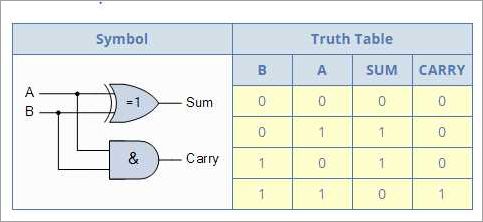
A half adder is a basic building block in digital circuits that performs addition on two binary inputs. It consists of two Boolean logic gates, an XOR gate and an AND gate, which together calculate the sum and carry outputs. The half adder has two inputs, labeled A and B, and two outputs, labeled SUM and CARRY.
The truth table for a half adder displays all possible combinations of inputs and their corresponding outputs. It shows that the SUM output is the XOR function of the inputs, while the CARRY output is the AND function of the inputs. This means that the SUM output represents the binary sum of the inputs, while the CARRY output indicates whether there is a carry bit from the addition.
In digital circuits, half adders are often used in combination with other half adders or full adders to perform arithmetic operations on binary numbers. By cascading multiple half adders together, it is possible to add multiple bits at a time and generate carry flags for multi-digit addition.
The combinational function of a half adder makes it an essential component in digital circuits. It allows for the addition of two binary numbers, bit by bit, by generating both the sum and carry outputs. This functionality is crucial in various applications, such as arithmetic operations in computers and calculators.
Overall, half adders play a crucial role in digital circuits by providing a simple and efficient method for adding binary numbers. They utilize Boolean logic gates to calculate the sum and carry outputs based on the inputs, allowing for the addition of binary digits in a systematic way.
Recognizing the Limitations of Half Adders

When working with digital circuits, it is important to understand the limitations of the components used. One such component is the half adder. A half adder is a combinational logic function that is used to add two binary bits together, producing a sum and a carry output. While the half adder is a fundamental building block in digital circuits, it has some inherent limitations that can affect its functionality.
One limitation of the half adder is that it can only add two binary bits. This means that if you want to add larger binary numbers, you would need to use multiple half adders or a more complex adder such as a full adder. The half adder’s inability to handle more than two inputs restricts its use in more complex arithmetic operations.
Another limitation is that the half adder does not have any built-in mechanism to handle carry operations. The carry output of a half adder can be used as an input to another adder to perform multi-bit addition, but the half adder itself cannot generate or propagate carry signals. This means that if there is a carry from the previous bit addition, the half adder cannot account for it.
Another limitation is that the outputs of a half adder are boolean values, representing either a 0 or a 1. While this is useful for basic arithmetic operations, it does not provide any information about overflow or underflow conditions. Flags such as overflow and carry flags are commonly used in more advanced arithmetic operations to indicate if a result is within the valid range of numbers.
Despite these limitations, the half adder is still an important component in digital circuits. It forms the basis for more complex adders and is an essential part of any arithmetic unit. By recognizing the limitations of the half adder, engineers can design circuits that overcome these limitations and perform more complex operations.
FAQ about topic “Exploring the Half Adder Truth Table: Unraveling the Logic of Half Adders”
What is a half adder?
A half adder is a digital circuit that adds two binary digits (bits). It has two inputs, called A and B, and two outputs, called Sum and Carry. The half adder can add two single-bit binary numbers and produce the sum and carry as outputs.
How does a half adder work?
A half adder works by performing the basic addition operation on two binary digits. It uses the XOR gate to produce the sum output and the AND gate to produce the carry output. The sum output is the result of the addition of the two input bits, and the carry output represents any carry-over that occurs during the addition.
Can a half adder handle carry-over from previous additions?
No, a half adder cannot handle carry-over from previous additions. It can only add two input bits and produce the sum and carry outputs for those two bits. If there is a carry-over from a previous addition, a full adder is required.
What are the applications of half adders?
Half adders are used in various applications, including digital arithmetic circuits, computer processors, and data communication systems. They are the building blocks for more complex adder circuits, such as full adders and ripple carry adders. Half adders are also used in binary-to-BCD converters, which are used in decimal arithmetic operations.