The 2-bit adder is a fundamental logic circuit that performs the operation of adding two binary numbers together. It is comprised of logic gates such as AND, XOR, and OR, which take in two input bits and produce an output bit. The truth table of a 2-bit adder illustrates the relationship between the input bits and the output bits for all possible combinations.
The inputs of the 2-bit adder are the two binary numbers being added, represented as A0 and B0 for the least significant bits, and A1 and B1 for the most significant bits. The outputs of the adder are the sum bits, represented as S0 for the least significant bit and S1 for the most significant bit. The carry output, represented as C, indicates whether there is a carry-over from the addition.
The truth table for the 2-bit adder shows the possible combinations of the input bits and the corresponding output bits. The output bit S0 is the result of adding A0 and B0, while the output bit S1 is the result of adding A1, B1, and the carry input C. The carry output C is the result of any carry generated from adding A0, B0, and the carry input C. The zero output, represented as Z, is set to 1 when all the sum bits are equal to zero.
Understanding the truth table of the 2-bit adder allows us to comprehend the inner workings of the circuit and the logic behind addition in binary numbers. By analyzing the relationships between the input bits and the output bits, we can gain insight into how the adder performs the summing operation and determines the carry and zero outputs. This knowledge is crucial in designing more complex circuits and systems that involve binary addition.
Contents
- 1 Why Understand the 2 Bit Adder Truth Table?
- 2 Importance of Understanding the 2 Bit Adder Logic
- 3 Applications of the 2 Bit Adder
- 4 Components of the 2 Bit Adder
- 5 The 2 Bit Adder Truth Table Explained
- 6 Representation of Binary Addition
- 7 Truth Table for the 2 Bit Adder
- 8 The Role of Gates in the 2 Bit Adder
- 9 Overview of Logic Gates
- 10 Logic Gates in the 2 Bit Adder
- 11 Building and Testing a 2 Bit Adder Circuit
- 12 Designing the Circuit
- 13 Testing and Verifying the Circuit
- 14 FAQ about topic “Understanding the Logic Behind Addition with a 2 Bit Adder Truth Table”
- 15 What is a 2 bit adder?
- 16 How does a 2 bit adder work?
- 17 What is a truth table?
- 18 What is the purpose of a 2 bit adder truth table?
- 19 Why is it important to understand the logic behind addition?
Why Understand the 2 Bit Adder Truth Table?
The 2 Bit Adder Truth Table is an essential tool for understanding the logic behind addition in binary systems. By studying this table, we can grasp the fundamental principles of how binary numbers are added together using logic gates and Boolean algebra.
One of the key components in the 2 Bit Adder is the XOR gate, which stands for exclusive OR. This gate performs an operation that outputs a 1 only when the input bits are different. This gate plays a crucial role in summing the two bits being added.
Another important gate in the 2 Bit Adder is the AND gate, which outputs a 1 only when both input bits are 1. This gate is used to determine the carry bit, which is needed when adding two binary numbers. The carry bit represents a “carry over” from one column to the next, just like carrying over a digit in decimal addition.
The truth table for the 2 Bit Adder shows all the possible combinations of input bits and their corresponding output bits. This table allows us to understand how the logic gates perform their operations based on the binary inputs.
By analyzing the truth table, we can see that the sum of two binary bits can be either 0 or 1. However, there is also the possibility of a carry bit, which can be either 0 or 1. This information is crucial for understanding how binary numbers are added together using the 2 Bit Adder.
In summary, understanding the 2 Bit Adder Truth Table is essential because it provides insights into the logic behind addition in binary systems. By studying this table, we can grasp the fundamental principles of how bits are summed using XOR and AND gates, as well as the concept of carry bits. This knowledge is fundamental for working with binary numbers and performing arithmetic operations in computer systems.
Importance of Understanding the 2 Bit Adder Logic
The 2 bit adder is a fundamental building block in digital computer circuits. Understanding its logic is essential for anyone involved in designing or troubleshooting digital systems. The 2 bit adder is used to perform addition of two binary numbers, and its operation is based on the concepts of logical AND, OR, XOR, and half-adder.
By understanding the logic behind the 2 bit adder, one can grasp how binary numbers are added together. The adder takes two inputs, each representing a single bit, and produces two outputs: the sum and the carry. The sum output represents the sum of the two inputs, while the carry output indicates whether there was a carry-over from the previous bit addition.
The logic behind the 2 bit adder is based on the truth table, which shows all possible combinations of input bits and their corresponding outputs. This truth table helps to visualize the different logical conditions that can occur during the addition process.
Furthermore, understanding the 2 bit adder logic allows for the design of more complex circuits that involve multiple adders. By cascading multiple 2 bit adders, one can create adders with higher bit capacities, such as 4 bit, 8 bit, or even 16 bit adders. This knowledge is invaluable in modern computing systems where large numbers of binary numbers need to be added quickly and efficiently.
In summary, understanding the logic of the 2 bit adder is crucial for anyone involved in digital system design or troubleshooting. It forms the foundation for performing binary addition and enables the design of more complex circuits. By grasping the concepts of logical AND, OR, XOR, and half-adder, one can effectively work with binary numbers and utilize 2 bit adders in various applications.
Applications of the 2 Bit Adder
The 2-bit adder is a fundamental digital circuit that plays a crucial role in binary addition operations. It allows for the addition of two binary numbers, each containing 2 bits. The adder utilizes the XOR (exclusive OR) operation to calculate the sum bit, and the AND operation to determine the carry bit.
One of the main applications of the 2-bit adder is in arithmetic circuits. By combining multiple 2-bit adders, larger numbers can be added together. For example, a 4-bit adder would consist of two 2-bit adders connected in series. This allows for the addition of 4-bit binary numbers, greatly expanding the range of values that can be represented.
The output of a 2-bit adder consists of two bits: the sum bit and the carry bit. The sum bit represents the result of the addition operation, while the carry bit indicates whether there is a carry-over from the addition of the previous bit. These output bits can be utilized in various ways depending on the specific application.
In addition to arithmetic circuits, the 2-bit adder can also be used in a variety of other applications. For example, it can be employed in error detection and correction mechanisms. By summing up the individual bits of a binary data set, discrepancies or errors can be identified and corrected through additional logic circuits.
Another area where the 2-bit adder finds application is in Boolean logic operations. By using the sum and carry bits as inputs, complex logic functions can be implemented. For instance, the sum bit can be used as an output to represent the logical OR operation, while the carry bit can act as an output for the logical AND operation.
In summary, the 2-bit adder is a versatile digital circuit with applications in arithmetic circuits, error detection and correction mechanisms, and Boolean logic operations. Its capability to perform binary addition, along with the generation of sum and carry outputs, makes it an essential component in numerous digital systems and electronic devices.
Computing
In the field of computing, truth tables and logic gates are fundamental tools used to understand and analyze the logic behind various operations. These operations can range from basic logical operations such as AND, OR, and XOR, to more complex tasks such as arithmetic operations like addition.
One of the key components in arithmetic operations is the adder, which is a digital circuit that combines two binary numbers and produces their sum. A half adder is a type of adder that takes two binary inputs, usually represented as 0s and 1s, and produces a sum and a carry output.
The inputs to a half adder can only be either 0 or 1, representing the two possible binary values. The output of a half adder consists of the sum of the two inputs and a carry, which is a bit that is carried over to the next stage of the addition process if necessary.
A truth table is a tabular representation of the possible inputs and their corresponding outputs for a given logical operation. In the case of a half adder, the truth table would list all possible combinations of inputs (0,0; 0,1; 1,0; 1,1) and the resulting outputs (0,0; 0,1; 0,1; 1,0) for the sum and carry.
By analyzing the truth table of a half adder, one can understand the logic behind the addition operation and how the sum and carry outputs are determined based on the input bits. This understanding forms the basis for designing and implementing more complex adders and arithmetic circuits in computing systems.
Binary Arithmetic
Binary arithmetic is a fundamental concept in computer science and digital electronics. It involves performing mathematical operations, such as addition, subtraction, multiplication, and division, on binary numbers – numbers that consist only of zeros and ones.
One of the most basic operations in binary arithmetic is addition. The process of adding two binary numbers together is similar to adding decimal numbers, but with a few key differences. In binary addition, the sum of two binary digits can only be either 0 or 1. When summing two binary digits, if the result is 2 or higher, a carry operation is needed.
A half adder is a simple circuit that performs binary addition on two bits. It has two inputs, one for each bit, and two outputs – the sum and the carry. The sum output represents the result of adding the two input bits together, while the carry output indicates whether a carry operation is required.
The truth table for a half adder shows all possible combinations of input bits and the resulting output values. For example, if both input bits are 0, the sum and carry outputs are also 0. Conversely, if both input bits are 1, the sum output is 0 and the carry output is 1. The half adder’s logic is based on the XOR and AND operations, which are fundamental logic operations in binary arithmetic.
In binary arithmetic, the concept of a carry is crucial. When performing addition on multi-bit numbers, a carry can propagate from one bit to the next. To perform addition on two multi-bit numbers, a full adder is used. A full adder has three inputs – two for the bits being added and one for the carry from the previous bit. It produces two outputs – the sum of the three input bits and the carry that will be propagated to the next bit.
By combining multiple full adders, it is possible to perform addition on binary numbers of any length. Each full adder processes one bit of the numbers being added, and the carry output from each full adder becomes the carry input for the next adder. This allows for the addition of numbers with multiple bits, such as 8-bit, 16-bit, or even larger numbers.
In conclusion, binary arithmetic is a fundamental operation in computer science and digital electronics. It involves performing mathematical operations on binary numbers using logic gates, such as XOR and AND gates. The concept of a carry is essential for addition and allows for the processing of multi-bit numbers. Understanding binary arithmetic is crucial for working with binary numbers in computer programming and digital circuit design.
Components of the 2 Bit Adder

The 2 Bit Adder is a key component in binary addition, which is a fundamental operation in digital logic. It is used to add two binary numbers, bit by bit, producing a sum and a carry output. The adder consists of multiple logic gates, such as XOR and AND gates, that perform specific operations on input bits.
The main logic gate used in the 2 Bit Adder is the XOR gate. This gate takes two binary inputs and outputs a binary result. It performs the exclusive OR operation, which returns a 1 if one and only one of the inputs is 1, and a 0 otherwise. The XOR gate is used to calculate the sum of the two input bits in the adder.
Another important logic gate used in the adder is the AND gate. This gate takes two binary inputs and outputs the logical AND operation between them. It returns a 1 only if both inputs are 1, otherwise it returns a 0. The AND gate is used to calculate the carry output in the adder.
The 2 Bit Adder has two input bits, A and B, which represent the binary numbers to be added. These bits are connected to each XOR and AND gate in the adder to perform the necessary calculations. The sum output is the result of the XOR operation, while the carry output is the result of the AND operation.
In the truth table of the 2 Bit Adder, each combination of input bits (A and B) produces a specific output value for the sum and carry. The sum output is represented by a single bit, and the carry output is represented by another single bit. The truth table shows all the possible combinations and their corresponding outputs, allowing us to understand the logic behind the addition operation.
In conclusion, the 2 Bit Adder consists of XOR and AND gates that perform summing and carry operations on two input bits. It calculates the sum and carry outputs, which represent the result of binary addition. Understanding the components and their functions in the adder is crucial in comprehending the logic behind binary addition.
Half Adder
A half adder is a digital circuit that performs the operation of adding two binary digits. It has two inputs: A and B, and two outputs: sum (S) and carry (C). The half adder can only add two bits and does not take into account any carry from previous addition operations.
The half adder uses the xor (exclusive or) operation to calculate the sum and the and operation to calculate the carry. The sum output (S) is true when there is only one input that is true, representing the digit to be added. The carry output (C) is true when both inputs are true, indicating a carry to the next position.
The truth table for a half adder shows all possible combinations of input values and their corresponding outputs. When both inputs (A and B) are zero, the sum (S) is also zero. When one input is one and the other is zero (or vice versa), the sum (S) is one. When both inputs are one, the sum (S) is zero and the carry (C) is one.
| A | B | S | C |
|---|---|---|---|
| 0 | 0 | 0 | 0 |
| 0 | 1 | 1 | 0 |
| 1 | 0 | 1 | 0 |
| 1 | 1 | 0 | 1 |
In summary, a half adder is a basic building block in binary arithmetic. It can add two binary bits together and provide the sum and carry outputs. The sum output represents the ones place digit, while the carry output represents the tens place digit. Working together, multiple half adders can be combined to create a full adder, allowing for the addition of multiple bits.
Full Adder
A Full Adder is a logic circuit that performs the addition operation on two binary bits, as well as accounting for a carry input from a previous stage. It is an essential component in the design of complex digital systems that involve adding binary numbers.
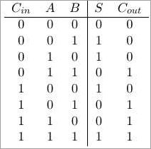
The Full Adder takes in three inputs: two input bits, A and B, and a carry input, C. It generates two outputs: the sum (S) and the carry output (Cout).
The sum output (S) of the Full Adder is determined using the XOR (exclusive OR) logic gate. The XOR gate outputs a logic high (1) if one and only one of its inputs is high. In the context of a Full Adder, the XOR gate calculates the sum bit (S) of the two input bits.
The carry output (Cout) of the Full Adder is determined using a combination of AND and OR logic gates. The two input bits (A and B) are fed into an AND gate, which outputs a logic high (1) only if both inputs are high. The carry input (C) is also fed into an AND gate with the two input bits inverted. The outputs of these two AND gates are then fed into an OR gate to produce the carry output (Cout).
The truth table for a Full Adder is a combination of inputs and corresponding outputs. It shows all the possible input combinations and the resulting outputs for the sum and carry outputs. This truth table is essential for understanding the logic behind a Full Adder and can be used to verify its correctness through summing all possible input combinations.
In summary, a Full Adder is a crucial component in digital systems for adding binary numbers, taking into account input bits and previous carry inputs. It uses XOR, AND, and OR logic gates to generate the sum and carry outputs. The truth table of a Full Adder can be used to understand its functioning and verify its correctness.
The 2 Bit Adder Truth Table Explained
A 2-bit adder is a basic digital circuit used to perform the addition operation on two binary numbers. It is called a “2-bit” adder because it can add two binary numbers with two binary digits each.
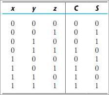
The truth table of a 2-bit adder shows the possible combinations of inputs and their corresponding outputs. The inputs are labeled as A0, A1, B0, and B1, representing the bits of the two binary numbers being added. The outputs are labeled as S0 and S1, representing the sum bits, and C, representing the carry bit.
The 2-bit adder uses basic logic gates, such as XOR and AND, to perform the addition operation. The XOR gate is used to calculate the sum bits, while the AND gate is used to calculate the carry bit. The XOR gate outputs “1” when the inputs are different, and “0” when the inputs are the same. The AND gate outputs “1” only when both of its inputs are “1”.
For each combination of inputs, the 2-bit adder truth table shows the corresponding outputs. The sum bits are obtained by applying the XOR operation to the corresponding input bits. The carry bit is obtained by applying the AND operation to the corresponding input bits. The carry bit from the previous bit is also considered in the calculation of the sum and carry bits.
The truth table of a 2-bit adder has four rows, each representing a different combination of inputs. The input bits can take on the values of 0 or 1. For each row, the sum bits and the carry bit are calculated based on the input values. The sum bits represent the binary sum of the two input bits, while the carry bit represents the carry-over from the previous addition operation.
In summary, the 2-bit adder truth table explains the logic behind addition using binary numbers. It shows how the sum and carry bits are calculated based on the input values using XOR and AND operations. Understanding the truth table is essential for designing and analyzing digital circuits that perform addition operations.
Representation of Binary Addition
The representation of binary addition is a fundamental concept in computer science and digital electronics. In binary addition, we use an adder circuit to perform the operation of addition on two binary numbers. The adder takes in two input bits and produces two output bits – a sum and a carry.
The input bits represent the binary numbers that we want to add together. Each input bit can be either a 0 or a 1. The summing operation is performed on these input bits using logic gates such as AND, XOR, and OR gates. These gates manipulate the input bits to produce the sum and carry outputs.
The sum output represents the result of adding the input bits together. It can be either a 0 or a 1, depending on the values of the input bits and the carry. The carry output represents the carry-over from one bit to the next in the addition process. If the sum of the input bits exceeds the maximum value that can be represented by a single bit, a carry is generated and passed to the next bit.
A 2-bit adder truth table shows all the possible combinations of input bits and their corresponding output values. It helps us understand the logic behind binary addition and how the carry and sum outputs are generated based on the input bits. The truth table includes columns for the input bits, carry, sum, and the expected output values for each combination of input bits.
In a half adder, the carry output is generated by performing an AND operation on the input bits. The sum output is generated by performing an XOR operation on the input bits. This half adder logic is then expanded to a full adder to handle carry propagation between multiple bits in larger addition operations.
Binary addition is a fundamental operation in computer arithmetic and is used extensively in digital systems. Understanding the representation of binary addition is crucial for designing and implementing efficient adder circuits and performing accurate addition operations in computers and other digital devices.
Truth Table for the 2 Bit Adder
The truth table for the 2 bit adder represents the logic and operation of adding two binary numbers, each represented by 2 bits. The adder has two inputs – “A” and “B” representing the binary numbers to be added, and two outputs – “sum” and “carry”, representing the sum and carry bits generated during the addition operation.
The truth table shows all possible combinations of inputs and their corresponding outputs. It is a comprehensive representation of the logic implemented by the adder. Each row in the truth table represents one possible combination of input values.
The “sum” output represents the bitwise sum of the two input bits. It is calculated using the XOR logic gate, which performs the addition operation without considering the carry. The “carry” output represents the carry bit generated during the addition operation. It is calculated using the AND logic gate, which performs a bitwise AND operation on the input bits.
The truth table shows that when both input bits are zeros (0), the “sum” output is also zero (0) and the “carry” output is zero (0). In this case, there is no carry generated during the addition operation. When both input bits are ones (1), the “sum” output is zero (0) and the “carry” output is one (1). In this case, there is a carry generated during the addition operation.
The truth table also shows all possible combinations of inputs and their corresponding outputs for all other cases. It provides a clear representation of the logic implemented by the 2 bit adder and helps in understanding the concept of binary addition.
Input and Output Variables
In the context of a 2-bit adder, input and output variables play a crucial role in understanding the logic behind addition. The input variables are the binary values that are being added together, while the output variables represent the result of the addition operation.
The input variables in a 2-bit adder are typically labeled as A0, A1, B0, and B1, where A0 and A1 are the individual bits of the first input number, and B0 and B1 are the individual bits of the second input number. These input variables can have a value of either zero or one, representing the binary digits in the numbers being added.
The output variables in a 2-bit adder are usually labeled as S0 and S1, representing the sum of the input variables. These output variables are calculated using the XOR (exclusive OR) logic operation. The XOR operation takes two binary inputs and outputs a binary value of one if the inputs are different, and a binary value of zero if the inputs are the same.
In addition to the sum output variables, a 2-bit adder also has a carry output variable, labeled as C. The carry output represents the carry that occurs when the sum of two bits is greater than one. The carry output is calculated using the AND and OR logic operations. The AND operation outputs a binary value of one if both of its inputs are one, while the OR operation outputs a binary value of one if either of its inputs are one.
The truth table for a 2-bit adder contains all possible combinations of the input variables and the corresponding sum and carry outputs. This truth table is used to determine the logic behind the addition operation and serves as a reference when constructing the 2-bit adder circuit. It allows for a systematic analysis and verification of the logic involved in summing two binary numbers.
Understanding the Logic Behind Addition
In the field of computer engineering, addition is a fundamental operation that forms the basis of many complex calculations. Understanding the logic behind addition is crucial for designing efficient circuits and algorithms. A 2-bit adder is a simple circuit that can add two binary numbers together. It takes two inputs, each representing a single bit of the numbers to be added, and produces two outputs: the sum bit and the carry bit. The sum bit represents the result of the addition, while the carry bit indicates if there was a carry-over from the previous bit.
The 2-bit adder uses a combination of logical operations, such as XOR, OR, and AND, to compute the sum and carry bits. The XOR gate outputs a logical 1 if and only if the inputs are different, which is used to calculate the sum bit. The OR gate outputs a logical 1 if any of the inputs are 1, which is used to calculate the carry bit. And the AND gate outputs a logical 1 only if all of its inputs are 1, which is used to determine if there is a carry-over.
For example, let’s consider the inputs 1 and 0. The XOR gate will output 1, indicating that the sum bit is 1. The OR gate will also output 1, indicating that there is a carry-over. This is because when adding 1 and 0, there is a carry-over from the first bit. The carry bit will be 1, indicating the presence of a carry-over.
The truth table for the 2-bit adder shows all possible input combinations and their corresponding output values. It is a useful tool for understanding the logic behind addition and can be used to verify the correctness of the adder circuit. The table lists all possible combinations of the input bits, and the corresponding sum and carry bits. It helps in understanding the relationship between the input and output bits and can be used to identify any errors in the circuit design.
In conclusion, understanding the logic behind addition is essential for computer engineering. The use of logical operations like XOR, OR, and AND, allows the 2-bit adder to compute the sum and carry bits accurately. The truth table provides a comprehensive overview of the adder’s behavior, making it an invaluable tool for verifying its correctness and ensuring accurate calculations in the binary system.
The Role of Gates in the 2 Bit Adder
In the binary addition operation, logic gates play a crucial role in enabling the 2 bit adder to perform its function. The adder consists of two half adders and a full adder, each of which utilizes different types of gates to process the input and produce the output.
Starting with the half adder, it takes in two input bits and produces two outputs: the sum and the carry. The sum output is generated using an XOR gate, which performs the exclusive OR operation on the input bits. The carry output, on the other hand, is produced by an AND gate, which performs the logical AND operation on the input bits. These gates ensure that the half adder correctly adds the input bits and generates the necessary output.
In the case of the full adder, it takes in three input bits: two bits from the previous stage and a carry bit. It then produces two outputs: the sum and the carry. Similar to the half adder, the sum output is generated using an XOR gate, which operates on the input bits. Additionally, there is an OR gate involved in the process. It takes the outputs of the XOR gate as well as the carry input and produces the final sum output. The carry output, again, is produced by an AND gate, which performs the logical AND operation on the input bits. These gates ensure that the full adder correctly adds the three input bits and generates the necessary output.
By using these different logic gates in the 2 bit adder, the binary addition operation becomes possible. The gates enable the adder to process the input bits and perform the necessary logical operations to produce the correct output bits, which represent the sum and the carry. The truth table for the adder showcases the role of these gates in the addition process, as it demonstrates the different combinations of input bits and their corresponding output bits.
Overview of Logic Gates
In digital electronics, logic gates are fundamental building blocks that perform basic operations on binary inputs (0s and 1s) to produce a binary output. These gates are the building blocks of complex digital circuits and are used in various applications like computers, calculators, and digital communication systems.
There are several types of logic gates, each with its own unique function. The most common logic gates are the AND gate, OR gate, XOR gate, and NOT gate. These gates operate on single or multiple input bits and perform logical operations like addition, subtraction, multiplication, and division.
The AND gate is a basic logic gate that produces a high output (1) only when all of its inputs are high (1). It can be represented using the mathematical symbol “&” or by the word “AND.” The OR gate, on the other hand, produces a high output (1) when any of its inputs are high (1). It can be represented using the mathematical symbol “|” or by the word “OR.”
The XOR gate, also known as the exclusive OR gate, produces a high output (1) when there is an odd number of high inputs (1). It can be represented using the mathematical symbol “^” or by the word “XOR.” The NOT gate, also known as the inverter, produces the complement of its input. If the input is high (1), the output will be low (0), and vice versa.
Logic gates can be combined in various ways to create complex circuits, such as the half adder and full adder. These adder circuits are used to perform binary addition, where two binary digits (bits) are added together to obtain a sum and a carry digit. The truth table of a logic gate shows the relationship between its input and output states.
In summary, logic gates are the fundamental building blocks of digital electronics. They perform logical operations on binary inputs to produce binary outputs. Understanding the logic behind these gates is crucial in designing and analyzing digital circuits, as well as in understanding the operation of various digital systems.
Logic Gates in the 2 Bit Adder
In a 2 Bit Adder, the logic gates play a crucial role in the addition operation. These gates are electronic circuits that perform specific logic functions, such as AND, OR, and XOR. By combining these gates, we can create a complex circuit that adds two 2-bit binary numbers together.
At the input of the 2 Bit Adder, we have two sets of inputs – A0 and B0, and A1 and B1, representing the two binary numbers to be added together. The inputs are fed into the logic gates to create the sum and carry outputs. The sum outputs represent the result of the addition operation, while the carry outputs indicate if there is a carry-over to the next bit.
The AND gate in the 2 Bit Adder takes two inputs and produces an output of 1 only if both inputs are 1. This gate is used for the carry outputs to determine if there is a carry-over from the lower bit to the higher bit. The OR gate, on the other hand, produces an output of 1 if any of its inputs are 1. It is used to produce the sum outputs.
The XOR gate, also known as the exclusive OR gate, produces an output of 1 if the number of 1s in its inputs is odd. It is used in the summing operation of the 2 Bit Adder to determine whether a particular bit should be set to 1 or 0. The XOR gate is used in combination with other gates to create a half adder, which adds two single-bit numbers together.
By combining these logic gates in a specific arrangement, we can create a 2 Bit Adder that adds two 2-bit binary numbers together. The inputs are fed into the logic gates to produce the sum and carry outputs, which are the result of the addition operation. Through the use of these logic gates, complex binary addition can be performed efficiently and accurately.
AND Gate
An AND gate is a basic logic gate that performs the logical “AND” operation. It takes two input signals and produces an output signal based on the logical AND of the two inputs.
The AND gate has two input bits, often denoted as A and B, and one output bit, often denoted as Y. The output is a binary value that represents the logical AND of the input bits. The truth table for an AND gate is as follows:
| A | B | Y |
|---|---|---|
| 0 | 0 | 0 |
| 0 | 1 | 0 |
| 1 | 0 | 0 |
| 1 | 1 | 1 |
As shown in the truth table, the output Y is ‘1’ only when both input bits A and B are ‘1’. In all other cases, the output is ‘0’. This reflects the logical AND operation, where ‘1’ represents true and ‘0’ represents false.
The AND gate is an essential component in many logical operations and circuits. It is commonly used in combination with other gates, such as the XOR gate, to perform more complex operations. In the context of a 2-bit adder, the AND gate is used to calculate the carry and sum bits of the addition operation.
Overall, the AND gate is a fundamental building block of digital logic. Its logical operation allows for the manipulation and processing of binary data in electronic circuits.
OR Gate
An OR gate is a fundamental logic gate that operates on two binary inputs (0 or 1) and produces an output based on the logic operation of addition. The OR gate performs an addition operation and outputs a bit value of 1 if at least one of the inputs is 1, and a bit value of 0 only if both inputs are 0.
The truth table for an OR gate is as follows:
| Input A | Input B | Output |
|---|---|---|
| 0 | 0 | 0 |
| 0 | 1 | 1 |
| 1 | 0 | 1 |
| 1 | 1 | 1 |
As seen from the truth table, the output of an OR gate will be 1 if either or both inputs are 1, and the output will be 0 only if both inputs are 0. This logic operation can be represented by the symbol “+”, as in A + B.
When used within a half-adder or a full-adder circuit, the OR gate is responsible for producing the sum output. It takes the binary inputs and performs the logical OR operation, generating the sum bit.
In summary, the OR gate is a logic gate that outputs a bit value of 1 if at least one of the inputs is 1, and a bit value of 0 only if both inputs are 0. It is an essential component in the summing operation of a binary adder circuit.
XOR Gate
The XOR (exclusive OR) gate is a logical operation that performs a bitwise addition of two binary digits. It is a fundamental component of digital logic circuits and is often used in conjunction with other gates to perform complex tasks. The XOR gate takes two input bits and produces an output bit, referred to as the sum. The XOR operation returns a 0 when both input bits are the same (either both 0 or both 1), while it returns a 1 when the input bits are different.
In the context of a binary adder, the XOR gate is used to calculate the sum of two bits. When two bits are passed through an XOR gate, the output will be 1 if the two bits are different, and 0 if they are the same. This property makes the XOR gate ideal for performing addition in binary systems, where each bit represents a power of two.
In a half-adder circuit, which adds two binary digits together, the XOR gate is used to calculate the sum of the two bits. The output of the XOR gate represents the sum of the two bits, without considering any carry from previous bits. The XOR gate is also used in a full-adder circuit, which adds three binary digits together. In this case, the XOR gate is used to calculate both the sum and the carry.
The truth table for an XOR gate shows all possible input combinations and their corresponding output. When both input bits are 0, the output is 0. When both input bits are 1, the output is also 0. When the input bits are different (one is 0 and the other is 1), the output is 1. This behavior is consistent with the logical definition of the XOR operation.
In summary, the XOR gate is a crucial component in binary addition circuits. It allows for the calculation of the sum of two bits, considering their differences. The XOR gate operates on the principle that when the input bits are different, the output will be 1, and when the input bits are the same, the output will be 0.
Building and Testing a 2 Bit Adder Circuit
To build a 2 bit adder circuit, we need to understand the logic behind addition. In the binary system, addition is performed by summing the bits of two numbers, bit by bit, starting from the rightmost (least significant) bit. If the sum of two bits is 0 or 2, the output is 0, and if the sum is 1, the output is 1. This logic can be implemented using logic gates such as the OR, XOR, and AND gates.
The 2 bit adder circuit consists of two half adders and a full adder. A half adder is a circuit that adds two bits and produces a sum bit and a carry bit. The sum bit is the result of the XOR operation on the two input bits, and the carry bit is the result of the AND operation on the two input bits. The full adder takes into account the carry bit from the previous bit and adds it to the two input bits using the same logic as the half adder.
When testing the 2 bit adder circuit, we can use a truth table to verify the correctness of the circuit. The truth table lists all possible combinations of input bits and the corresponding output bits. For each combination, we can calculate the sum and carry bits using the logic described above, and compare them with the expected output from the truth table. This allows us to check if the circuit is working correctly for all possible inputs.
By building and testing a 2 bit adder circuit, we can gain a better understanding of how binary addition works and how logic gates can be used to perform this operation. This knowledge is fundamental in the field of digital electronics and can be applied in various applications such as computer architecture, data processing, and communication systems.
Designing the Circuit
To design a 2-bit adder circuit, we need to understand the logic behind addition. The circuit will take in two binary inputs, each representing a bit, and produce two outputs: the sum and the carry. To do this, we can create a truth table that shows the outputs for each possible combination of inputs.
The truth table will have four rows, corresponding to the possible combinations of inputs: 00, 01, 10, and 11. For each row, we need to determine the corresponding outputs. The sum output is the result of the binary addition operation, while the carry output represents the carry bit that is propagated to the next stage of the adder.
To calculate the sum output, we can use a XOR logic gate. The XOR gate takes two inputs and produces a high output (logic 1) only when the inputs are different. In our case, we can use the XOR gate to calculate the sum of the two input bits.
The carry output is a bit more complex. It is produced by a combination of AND and OR logic gates. The AND gate takes two inputs and produces a high output only when both inputs are high. The OR gate, on the other hand, produces a high output if at least one of the inputs is high.
In our 2-bit adder circuit, we can use two half adders to calculate the sum and the carry. Each half adder takes two inputs and produces a sum and a carry. The carry from the first half adder is then used as an input to the second half adder. Finally, the sum and carry outputs from the second half adder represent the final outputs of the circuit.
By combining the XOR and AND gates in the right way, we can create a circuit that performs binary addition. The truth table helps us determine the correct output for each combination of inputs, allowing us to verify the correctness of our circuit.
Using Logic Gates
In the context of the topic “2 Bit Adder Truth Table: Understanding the Logic Behind Addition,” logic gates play a crucial role in performing the addition operation. These gates are fundamental building blocks of digital circuits and can be used to implement various logical operations.
An adder is a combinational circuit that adds two binary numbers and produces a binary sum along with a carry. It takes inputs in the form of bits, which can be either 0 or 1. The logic gates perform the necessary computations to generate the sum and carry outputs.
The basic logic gates used in an adder circuit are AND, OR, and XOR gates. The AND gate produces an output of 1 only when all of its input bits are 1, while the OR gate produces an output of 1 if any of its input bits is 1. The XOR gate, also known as the exclusive OR gate, produces an output of 1 if and only if exactly one of its input bits is 1.
In a 2-bit adder, two half adders combine to form a full adder. Each half adder takes two input bits and produces two output bits: the sum and carry. The carry generated from the first half adder is fed into the second half adder along with the third input bit. The sum output from the second half adder is the final sum of the two binary numbers.
By employing these logic gates, the adder circuit performs the binary addition operation. The inputs are passed through the gates, and the logical operations are performed to determine the sum and carry outputs. The resulting output is a binary number that represents the sum of the two input numbers.
Truth tables are often used to represent the logic behind these operations. They provide a systematic way to present the possible input combinations and their corresponding outputs. In the case of the 2-bit adder, the truth table would include all possible combinations of the two input bits and the resulting sum and carry outputs.
Using logic gates in the design of an adder circuit allows for efficient and reliable binary addition. The gate configurations and their outputs can be carefully calculated to ensure accurate results. Understanding how these gates work together is essential in building more complex digital circuits and performing various arithmetic operations.
Connecting the Components
When it comes to understanding the 2-bit adder truth table, it’s important to understand how the different components are connected. In a 2-bit adder, there are two half-adders connected together to perform the addition operation. Each half-adder takes in two input bits, one from each number being added, and produces two outputs: the sum bit and the carry bit.
The carry bit from the first half-adder is then connected to the carry input of the second half-adder, allowing for the addition of the carry from the previous stage. This creates a ripple-carry effect, where the carry bit is propagated from one stage to the next. The sum output of the second half-adder is the final output of the 2-bit adder.
The half-adder itself is a basic logic circuit that performs the addition of two binary bits. It consists of two logic gates: an XOR gate and an AND gate. The XOR gate takes the two input bits and produces the sum bit, while the AND gate takes the two input bits and produces the carry bit.
To better understand the logic behind the half-adder, it’s helpful to refer to the truth table. The truth table shows all the possible combinations of input bits and their corresponding outputs. For example, when the two input bits are both 0, the sum bit is 0 and the carry bit is also 0. On the other hand, when the two input bits are both 1, the sum bit is 0 and the carry bit is 1.
In summary, by connecting the two half-adders together and using the carry bit from the previous stage, the 2-bit adder is able to perform binary addition. The sum bit is the final output of the adder, representing the result of the addition operation. The carry bit is used to carry over any overflow from one stage to the next, allowing for the addition of larger binary numbers.
Testing and Verifying the Circuit
To test and verify the 2-bit adder circuit, we need to analyze its logic and truth table. The half adder is a basic building block of the circuit, which can add two binary bits and produce two outputs: the sum bit and the carry bit. The input bits are represented as A and B, and the output bits are represented as SUM and CARRY. The logic behind the half adder operation is based on OR and XOR gates. The OR gate produces a high output if any of the input bits is high, while the XOR gate produces a high output if the input bits are different.
In the 2-bit adder circuit, we use two half adders and an additional OR gate to handle the carry bit. The carry output from the first half adder becomes an input to the second half adder, and the carry output from the second half adder is combined with the XOR output of the second half adder using the OR gate. The sum output of the first half adder is the least significant bit (LSB) of the binary sum, while the sum output of the second half adder is the most significant bit (MSB).
To verify the circuit, we can construct a truth table that lists all possible input combinations and their corresponding output values. For a 2-bit adder, there are four possible input combinations: 00, 01, 10, and 11. Each input combination is tested by applying the corresponding binary values to the A and B inputs of the circuit. The resulting sum and carry outputs are compared to the expected values based on the logic of the half adder operation.
The truth table allows us to verify the correctness of the circuit by checking if the actual outputs match the expected outputs for each input combination. If the outputs match, it confirms that the circuit is functioning correctly. If there are any discrepancies, it indicates a problem with the circuit design or implementation. Testing and verifying the circuit using the truth table is an essential step in ensuring its reliability and accuracy for binary addition operations.
Test Inputs
When testing a 2-bit adder, it is important to consider the various combinations of inputs that can be used to verify its logic and functionality. The inputs in this case refer to the binary digits or bits that are added together to produce an output.
The two inputs for the 2-bit adder can each take on the values of either 0 or 1. These inputs represent the bits that are being added together. For example, input A could be 1 and input B could be 0.
The output of the adder is a combination of a sum bit and a carry bit. The sum bit represents the result of the addition operation, while the carry bit indicates if there is an additional bit that needs to be carried over to the next column of the adder.
In terms of logic, the adder uses the XOR, AND, and OR operations to calculate the sum and carry bits. The XOR operation is used to determine the sum bit, the AND operation is used to determine the carry bit, and the OR operation is used to determine if there is a carry bit.
To test the 2-bit adder, one approach is to create a truth table that lists all possible input combinations and their corresponding outputs. This table helps in understanding how the adder performs the binary addition operation.
For example, the input A could be 0 and input B could be 0. In this case, the sum would be 0 and there would be no carry. Another example would be input A being 1 and input B being 1. In this case, the sum would be 0 and there would be a carry.
By systematically summing different inputs, it becomes possible to verify the logic and operation of the 2-bit adder. Testing all possible inputs provides a comprehensive understanding of how the adder works and ensures its accuracy and reliability.
Expected Outputs
In the context of a 2 Bit Adder, the expected outputs refer to the results that we anticipate getting when performing addition with the given inputs. These outputs depend on the values of the input bits and the carry bit, and they determine the final sum and carry bits after the addition operation.
The expected outputs consist of the sum bit and the carry bit. The sum bit represents the binary addition of the two input bits, while the carry bit indicates whether there is a carry-over from the previous bit addition.
For example, when both input bits are 0 and the carry bit is 0, the expected output for the sum bit would be 0, since 0 plus 0 equals 0. The carry bit would also be 0, as there is no carry-over in this case.
Similarly, if one input bit is 1 and the other is 0, the expected output for the sum bit would be 1, as 1 plus 0 equals 1. The carry bit would still be 0, since there is no carry-over.
However, if both input bits are 1 and the carry bit is 1, the expected output for the sum bit would be 0, because 1 plus 1 results in a binary value of 10. In this case, the carry bit would be 1, as there is a carry-over from the addition of the previous bit.
By analyzing the truth table of a 2 Bit Adder, which lists all possible combinations of input, carry and their corresponding outputs, we can determine the expected outputs for any given input and carry values. This understanding of the logic behind addition allows us to predict the correct sum and carry bits produced by the adder.
FAQ about topic “Understanding the Logic Behind Addition with a 2 Bit Adder Truth Table”
What is a 2 bit adder?
A 2 bit adder is a digital circuit that can add two binary numbers of two bits each. It is used in computer arithmetic operations.
How does a 2 bit adder work?
A 2 bit adder works by performing binary addition on two input bits and a carry bit. The sum output is the result of the addition, and the carry output is used to carry over if the addition results in a carry.
What is a truth table?
A truth table is a table that shows all possible combinations of inputs and their resulting outputs in a logical circuit. It is used to determine the behavior and functionality of the circuit.
What is the purpose of a 2 bit adder truth table?
The purpose of a 2 bit adder truth table is to show all possible inputs (bits A, B, and carry) and their corresponding outputs (sum and carry-out). It helps in understanding the logic and functionality of a 2 bit adder.
Why is it important to understand the logic behind addition?
Understanding the logic behind addition is important because addition is one of the fundamental operations in computer arithmetic. It is used in various applications, such as calculations, data processing, and programming. By understanding the logic, one can design and optimize efficient addition circuits and algorithms.